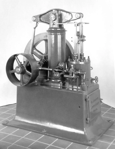
With the proliferation of steam power in the late 1800s, many inventors looked to create a simpler and more efficient engine. Rather than having combustion occur outside the engine, as with a steam engine, designers sought to create an internal combustion engine, in which the piston was driven by the expansion of a volatile gas mixture after it was ignited. George Brayton of Boston, Massachusetts was one such inventor, and while his designs would forever influence the internal combustion engine, he never achieved the same level of recognition as many of his contemporaries.
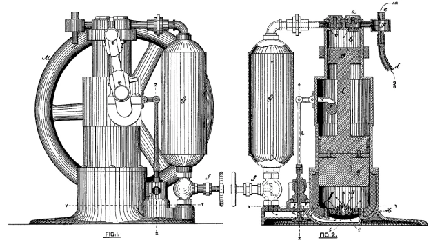
Patent drawings of George Brayton’s 1872 engine. Gas and air was drawn into cylinder C, compressed by piston D, and stored in reservoir G. The mixture was then released into cylinder A and ignited as it passed through wire gauze e. As the mixture combusted and expanded, it acted on piston B.
Brayton was an inventor, engineer, and machinist who had experience with steam engines. Some of his internal combustion engine experiments date back to the early 1850s, but he began serious development around 1870. In 1872, Brayton patented a new type of engine, the first in a series that became known as the Brayton Ready Motor. The name “Ready Motor” described the fact that the engine was immediately ready for operation, unlike a steam engine. The Brayton engine was also called a “Hydro-Carbon Engine.” The engine used fuel (hydrocarbons) mixed with air as the working fluid that directly acted on the piston, rather than the fuel heating some other working fluid, as with a steam engine. The theoretical process by which the Brayton engine worked became known as the constant-pressure cycle or Brayton cycle. The Brayton cycle in a piston engine involves the pressure in the engine’s cylinder being maintained by the continued combustion of injected fuel as the piston moves down on its power stroke. The constant-pressure Brayton cycle is used in gas turbines and jet engines and is also very similar to the Diesel cycle.
Brayton’s 1872 patent engine was a two-stroke that had two pistons mounted to a common connecting rod. The smaller of the two pistons acted as an air pump, compressing the air to around 65 psi (4.5 bar). A gaseous fuel, such as illuminating gas or carbureted hydrogen, was mixed with the air entering the compression cylinder. Alternatively, an oil fuel, such as naphtha, could be vaporized and added to the air entering the compression cylinder. The air/fuel mixture was then compressed, passed through a valve, and stored in a reservoir. An engine-driven camshaft opened a valve that allowed the pressurized air/fuel mixture to flow from the reservoir and into the large combustion cylinder. Before entering the cylinder, the air/fuel mixture passed through layers of wire gauze where a small pilot flame constantly burned. The pilot flame was kept lit by a continuous, small supply of the air/fuel mixture. As the charge passed through the wire gauze and entered the cylinder, it was ignited by the pilot flame. The combusting and expanding gases created around 45 psi (4.1 bar) of pressure that forced the large piston back in its cylinder, creating the power stroke. At the same time, the small piston was moved toward top dead center in its cylinder, compressing another charge of air for continued operation.

Brayton’s 1874 patent illustrating a double-sided piston. The upper side of piston B compressed air as the lower side was exposed to the combustion process of air and fuel being mixed and ignited in chamber H. Reservoir C only stored compressed air.
Brayton’s experience with steam engines and how steam expands into the cylinder to smoothly act on the piston probably influenced his desire to have the fuel burn in the cylinder. Gas expansion created by burning fuel acts smoothly on the piston, whereas the sudden ignition of fuel by a spark creates more of an explosion that exposes the piston and other engine components to high stresses. The combustion (motor) cylinder was about twice the volume of the compression (pump) cylinder, and the reservoir was no more than twice the volume of the combustion cylinder. The pressure in the reservoir was always greater than the pressure in the combustion cylinder. A water jacket surrounded the combustion cylinder to provide engine cooling.
While the 1872 patent illustrated an engine utilizing a separate compression piston, Brayton explained in the patent that the same principles of his engine could be applied utilizing both sides of the same piston. One side of the piston would compress the working fluid, while the other side of the piston would be driven by the expanding gases as the working fluid undergoes combustion. The patent drawing also shows a flywheel mounted to the camshaft. Engine power would be distributed from a driving pulley on the opposite end of the flywheel. However, images of early Brayton engines show an articulated rod mounted to the connecting rod that drove the flywheel and drive pulley.

Brayton Ready Motor vertical engine with a double-sided piston. The air reservoir was housed in the rocking beam support column. Note the ball governor.
Around 1873, Brayton installed a 4 hp (3.0 kW) engine in a streetcar in Providence, Rhode Island. The streetcar could obtain a speed of 15 mph (24 km/h), but it would barely move with a full load and had difficulty climbing an incline. A larger 12 hp (8.9 kW) engine was substituted, as it was the most powerful Brayton engine that fit in the space available. The engine took up the space of one passenger and enabled the streetcar to climb a 5 percent grade. All total, the streetcar was tested for 18 months. However, the tests indicated issues with wheel slip on the rails, especially in snow or ice, and financial issues brought an end to the experiment.
A drawback to the 1872 engine was the storage of the volatile gas mixture in the reservoir. If any flame were to get past the wire gauze and continue to burn back to the reservoir, the contents of the reservoir would explode. A safety valve prevented damage to the engine, but such an event was very disconcerting to anyone near the engine. The use of light, gaseous fuel exacerbated the issue. In 1874, Brayton switched to a heavy petroleum oil fuel and patented a refined engine in which only air was stored in the reservoir. A small supply of petroleum fuel was pumped into absorbent, porous material contained in a chamber that surrounded the induction pipe. The top of the chamber formed what was basically a burner. As the liquid fuel was heated by the engine and vaporized, it joined with the air charge being admitted into the cylinder via a camshaft-driven valve. The mixture was then ignited as it flowed through the burner section and into the cylinder. The burner stayed lit by residual fuel from the absorbent material mixing with a small amount of air from the reservoir that constantly passed through the burner.

Engine speed was controlled by an admission valve that regulated the amount of air passing into the cylinder. Although the fuel quantity supplied to the chamber was metered and dependent on engine speed, making changes to engine speed proved to be difficult. Any change in the amount of air supplied meant that there was a brief period of either too much or too little fuel, and this would occasionally extinguish the burner flame. By 1876, this issue had been resolved by implementing a new fuel injection process. The incoming air passed through the absorbent, porous material that was saturated with injected fuel. A jet of air coincided with the injection of fuel and helped distribute the fuel throughout the absorbent material. This injection technique proved more responsive than the earlier vaporization process.
Other changes incorporated in the 1874 engine were the use of both sides of the piston. A rod connected to the compression side of the piston extended out of the engine. The rod decreased the volume of the compression cylinder to less than that of the combustion cylinder. The rod also provided a means to harness power from the reciprocating movement of the piston. Although the rod was mounted on the compression side of the double-sided piston, it was the power stroke of the combustion side that provided the motive force.
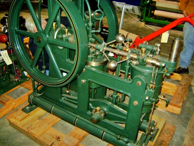
Circa 1876 Brayton inverted rocking beam engine. The combustion cylinder is on the left, and the smaller compression cylinder is at the center of the engine. Two air reservoirs made up the engine’s base; one was used for operating the engine, and the other was used for starting. The engine is currently in storage at the Smithsonian. (Woody Sins image via John Lucas / smokstak.com)
Development of the Brayton Ready Motor continued, and by 1875, the compression cylinder was completely separate from the combustion cylinder. Both cylinders had the same bore, but the stroke of the compression cylinder was about half that of the combustion cylinder. A number of different engine styles, both vertical and horizontal, were built, and the engines used different ways to harness the power of the compression cylinder. Some engines used the compression cylinder to actuate a rocking beam; other engines had the compression cylinder connected to a crankshaft that turned the power wheel.
By 1875 (and possibly as early as 1873), the Pennsylvania Ready Motor Company in Philadelphia had been established to sell Brayton’s engines, but the engines were built in the Exeter Machine Works in Exeter, New Hampshire. The Brayton Ready Motor may have been the first commercially available internal combustion engine. Engines based on the Brayton cycle were also sold by a number of other companies, including the New York & New Jersey Motor Company (by 1877) and Louis Simon & Sons, in Nottingham, England in 1878.
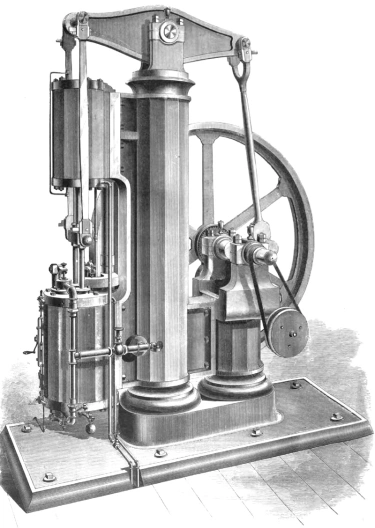
Drawing of the 10 hp (7.5 kW) vertical Brayton Ready Motor displayed at the Centennial Exposition in Philadelphia, Pennsylvania in 1876. This is the same engine that inspired George Selden. The compression cylinder was mounted above the combustion cylinder. The column supporting the rocking beam also contained the reservoir.
In 1878, John Holland used a 4 hp (3.0 kW) vertical Brayton engine in the first submarine powered by an internal combustion engine, the Holland I. While functional, this submarine was not a true success. Holland’s second submarine, the Fenian Ram, used a 15 hp (11.2 kW) horizontal Brayton engine and was launched in 1881. This submarine has been preserved and is displayed in the Paterson Museum in Paterson, New Jersey.
Also in 1878, a vertical engine was tested in an omnibus in Pittsburgh, Pennsylvania, but local authorities would not permit its use to transport passengers. Scottish engine pioneer Dugald Clerk converted a 5 hp (3.7 kW) Brayton engine to spark ignition. This engine was the first two-stroke, spark ignition engine ever built. Horizontal engines were installed in a few boats that operated on the Hudson River. In 1880, the USS Tallapoosa was fitted with a Brayton engine capable of 300 rpm. Other Brayton engines were used for industrial purposes such as powering pumps, cotton gins, or grinding mills. These Brayton engines were the first practical oil engines and were noted for their ease of starting and steady operation.
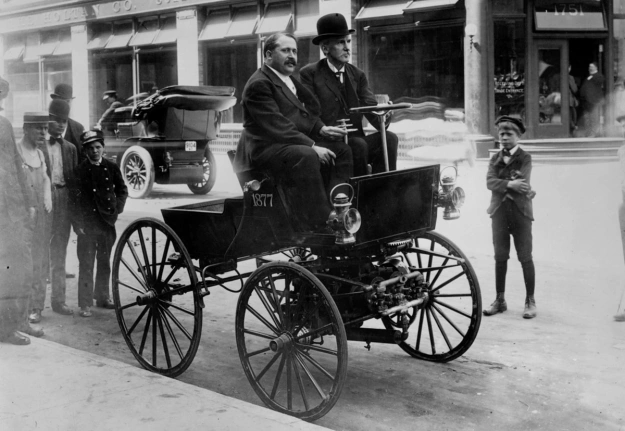
George Selden and Ernest Samuel Partridge in the Selden automobile in 1905. The vehicle was built in 1903 to prove the viability of Selden’s patent design. Between the front wheels is a three-cylinder Brayton-style engine, which ultimately led to Selden’s patent claims being dismissed.
George Selden was inspired by the 10 hp (7.5 kW) Brayton engine he saw at the 1876 Centennial Exposition in Philadelphia and felt the engine could be adapted to power a practical wheeled vehicle (automobile). In 1879, Selden applied for a patent on his three-cylinder Road Engine, which powered a four-wheel carriage. Selden continued to delay his patent with minor modifications until 1895, when the patent was finally granted despite the fact that Selden had never built the actual vehicle. That did not deter Selden from claiming he invented the automobile and demanding royalties from all automobile manufactures—suing those who refused to pay. Henry Ford led the rebellion against Selden and lost the court case in 1909. However, that ruling was overturned on appeal in 1911. For the successful appeal, Ford demonstrated that Selden’s automobile used an engine based on the Brayton cycle (two-stroke and a constant-pressure cycle), while Ford and others used engines based on the design of Nicolaus Otto (Otto cycle: four-stroke and a constant-volume cycle). No automobiles were built with a Brayton cycle engine; therefore, the automobile manufacturers were not infringing on Selden’s patent.
By the late 1880s, it was becoming clear that the Brayton cycle for piston-driven internal combustion engines was outclassed by the more efficient Otto cycle. The main issue facing the Brayton engine was its relatively low pressure (60–80 psi / 4.1–5.5 bar) combined with excessive friction, pumping, and heat losses between the compression and combustion cylinders.

Horizontal Brayton Ready Motor marine engine that was very similar, but not identical, to the engine used in the Fenian Ram submarine. The combustion cylinder is in the foreground, and the compression cylinder is in the background. The bevel gear powered the propeller shaft.
Brayton continued to develop his engine and applied for a patent in 1887 that outlined a horizontal, fuel injected, four-stroke engine. The cylinder was closed at both its combustion (hot) and non-combustion (cool) sides. Exhaust from the hot side of the cylinder passed through a water-cooled condenser that opened to the cool side of the cylinder. As the piston moved up on the exhaust stroke, the vacuum created in the cool side of the cylinder helped draw exhaust gases out of the hot side of the cylinder. An exhaust valve on the cool side of the cylinder was sprung to open at just above atmospheric pressure. As the piston moved toward the cool side of the cylinder on the intake stroke, the exhaust valve opened to expel the products of combustion. When the intake valve was opened, it brought fresh air into the cylinder and sealed the condenser. The intake valve then closed, and the piston moved toward the hot side of the cylinder to compress the air. Brayton stated in his patent that the cylinder’s cycle provided an abundance of fresh air to increase the engine’s power and efficiency.
Once the air was compressed, fuel was injected into the cylinder. The act of injecting the petroleum oil under pressure converted the fuel to a fine spray that was easily ignitable. The fuel injection pump was controlled by a follower riding on an engine-driven camshaft, and engine speed was controlled by the quantity of fuel injected. Once injected, the fuel was ignited by an incandescent burner made from a coil of platinum wire. This concept is very similar to a hot bulb in a much later semi-diesel engine. Brayton’s fuel injection was ideally suited for the use of heavy fuels. This engine was built with a 7 in (179 mm) bore and a 10 in (254 mm) stroke, displacing 385 cu in (6.31 L). Running at 200 rpm and driving a 30 in (762 mm) fan at 1,500 rpm for 10 hours, the engine only consumed 3.5 gallons (13.2 L) of kerosene.

Patent drawing showing the cylinder of Brayton’s horizontal, four-stroke engine of 1887. Passage d was used for both intake and exhaust. Passage d1 harnessed the vacuum created under the piston to help draw the exhaust gases out of the cylinder and through the condenser (C). The exhaust was expelled via valve g1. Fresh air was admitted via valve e1, which sealed the condenser. Fuel was injected via “Oil-jet” F and ignited by a platinum coil.
In 1890, Brayton patented his last engine, a vertical four-stroke that featured fuel injection. As the piston moved down on its intake stroke, a valve in the piston head opened and allowed air from the crankcase to enter the vacuum in the cylinder. As the piston moved up on the compression stroke, the exhaust valve opened for a short time to evacuate any remaining products of combustion. With all valves closed, the remaining air was compressed, and fuel was injected in a combustion chamber space above the piston. A connecting rod attached the piston to an inverted rocking beam, and the opposite end of the rocking beam was connected to a crankshaft. A small air pump was driven from a rod connected to the rocking beam. The air pump provided the pressure for the fuel injection system, enabling a blast of air to disperse the fuel into a fine spray as it was forced into the combustion chamber. The fuel was ignited by an incandescent burner and continued to burn as more fuel was injected and the piston moved down on the power stroke. Brayton’s last engine worked through a similar process as the engines Rudolf Diesel began developing in 1893, but Diesel used much higher cylinder pressures.
While traveling in England and still experimenting with engines, Brayton passed in 1892 at the age of 62. Production of his engines had already decreased by the time of his death but may have continued until the early 1900s. While names like Otto and Diesel are known to many today, Brayton’s is relatively unknown despite his pioneering work. Brayton’s engines were used in land vehicles, boats, and submarines before Otto’s or Diesel’s engines successfully ran. Undoubtedly, Brayton’s engineering contributions helped pave the way for many who followed. Out of the hundreds of Brayton Ready Motors that were made, only around six original engines are known to survive today.
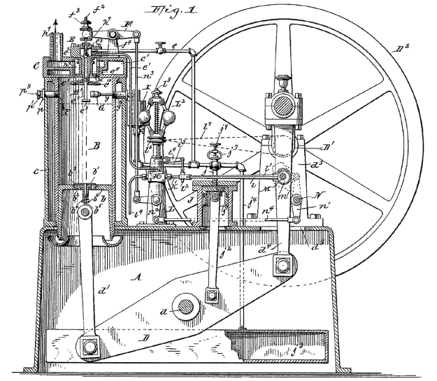
Patent drawing illustrating Brayton’s 1890 inverted rocking beam (D) engine. Air slightly pressurized in the crankcase (A) passed through a valve (b1) in the piston to fill the cylinder (B). Fuel was injected (via g) and ignited by a burner (G) in a combustion chamber space (B1) at the top of the cylinder. A smaller cylinder (J) acted as a pump to power the fuel injector.