Just after World War II, OKB-500 (Opytno-Konstruktorskoye Byuro-500 or Experimental Design Bureau-500) in Tushino (now part of Moscow), Russia was tasked with building the M-224 engine. The M-224 was the Soviet version of the Junkers Jumo 224 diesel aircraft engine. Many German engineers had been extradited to work on the engine, but the head of OKB-500, Vladimir M. Yakovlev, favored another engine project, designated M-501.

Front view of a 42-cylinder Zvezda M503 on display at the Technik Museum in Speyer, Germany. Unfortunately, no photos of the Yakovlev M-501 have been found, but the M503 was very similar. Note the large, water-jacketed exhaust manifolds. The intake manifold is visible in the engine Vee closest to the camera. (Stahlkocher image via Wikimedia Commons)
Yakovlev and his team had started the M-501 design in 1946. Yakovlev felt the M-224 took resources away from his engine, and he was able to convince Soviet officials that the M-501 had greater potential. All development on the M-224 was stopped in mid-1948, and the resources were reallocated to the M-501 engine.
The Yakovlev M-501 was a large, water-cooled, diesel, four-stroke, aircraft engine. The 42-cylinder engine was an inline radial configuration consisting of seven cylinder banks positioned around an aluminum crankcase. The crankcase was made up of seven sections bolted together: a front section, five intermediate sections, and a rear accessory section. The crankshaft had six throws and was supported in the crankcase by seven main bearings of the roller type.
Each cylinder bank was made up of six cylinders and was attached to the crankcase by studs. The steel cylinder liners were pressed into the aluminum cylinder block. Each cylinder had two intake and two exhaust valves actuated via roller rockers by a single overhead camshaft. The camshaft for each cylinder bank was driven through bevel gears by a vertical shaft at the rear of the bank. All of the vertical shafts were driven by the crankshaft. The pistons for each row of cylinders were connected to the crankshaft by one master rod and six articulating rods.

Rear view of a M503 on display at Flugausstellung L.+P. Junior in Hermeskeil, Germany. The upper cylinder gives a good view of the exhaust (upper) and intake (lower) manifolds, and the engine’s intake screen can just be seen between the manifolds as they join the compounded turbosupercharger. The exhaust gases exited the top of the turbine housing. (Alf van Beem image via Wikimedia Commons)
Exhaust was taken from the left side of each cylinder bank and fed through a manifold positioned in the upper part of the Vee formed between the cylinder banks. The exhaust flowed through a turbosupercharger positioned at the extreme rear of the engine. Exhaust gases expelled from the turbosupercharger were used to provide 551 lbf (2.45 kN / 250 kg) of jet thrust.
The pressurized intake air from the turbosupercharger was fed into a supercharger positioned between the turbosupercharger and the engine. The single-speed supercharger was geared to the crankshaft via the engine’s accessory section. Air from the supercharger flowed into a separate intake manifold for each cylinder bank. The intake manifold was positioned in the lower part of the Vee, under the exhaust manifold, and connected to the right side of the cylinder bank.
The M-501 had a 6.30 in (160 mm) bore and a 6.69 in (170 mm) stroke. The engine displaced 8,760 cu in (143.6 L) and produced 4,750 hp (3,542 kW) without the turbosupercharger. With the turbosupercharger and the thrust it provided, the engine produced 6,205 hp (4,627 kW). The engine weighed 6,504 lb (2,950 kg) without the turbocharger and 7,496 lb (3,400 kg) with the turbocharger.

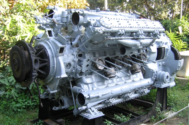
This partially disassembled M503 at the Naval Museum in Varna, Bulgaria gives some insight to the inner workings of the engine. The turbine wheel can be seen on the far left. Immediately to the right is the air intake leading to the compressor wheel, which is just barely visible in its housing. From the compressor, the air was sent through the seven outlets to the cylinder banks. The exhaust pipe can just be seen inside the water-jacketed manifold on the upper cylinder bank. Note the studs used to hold the missing cylinder bank. (Михал Орела image via Wikimedia Commons)
By 1952, the M-501 had been completed and had achieved over 6,000 hp (4,474 kW) during tests. The program was cancelled in 1953, as jet and turbine engines were a better solution for large aircraft, and huge piston aircraft engines proved impractical. The M-501 was intended for the four-engine Tupolev 487 and Ilyushin IL-26 and was proposed for the six-engine Tupolev 489. None of these long-range strategic bombers progressed beyond the design phase.
The lack of aeronautical applications did not stop the M-501 engine. A marine version was developed and designated M-501M. The marine engine possessed the same basic characteristics as the aircraft engine, but the crankcase casting were made from steel rather than aluminum. The M-501M was also fitted with a power take off, reversing clutch, and water-jacketed exhaust manifolds.
The exact details of the M-501M’s history have not been found. It appears that Yakovlev was moved to Factory No. 174 (K.E. Voroshilov) to further develop the marine engine design. Factory No. 174 was founded in 1932 and was formerly part of Bolshevik Plant No. 232 (now the GOZ Obukhov Plant) in Leningrad (now St. Petersburg). Factory No. 174 had been involved with diesel marine engines since 1945, and Yakovlev’s move occurred around 1958. Early versions of the marine engine had numerous issues that resulted in frequent breakage. In the 1960s, the engine issues were resolved, and Factory No. 174 was renamed “Zvezda” after the engine’s layout. Many languages refer to radial engines as having a “star” configuration, and “zvezda” is “star” in Russian. Zvezda produced the refined and further developed 42-cylinder marine engine as the M503.

Sectional rear view of a 42-cylinder Zvezda M503. The cylinder banks were numbered clockwise starting with the lower left; bank three had the master connecting rod. Note the angle of the fuel injector in the cylinder and that the injector pumps were driven by the camshaft (as seen on the upper left bank).
The Zvezda M503 retained the M-501’s basic configuration. The engine had a compounded turbosupercharger system with the compressor wheel connected to the crankshaft via three fluid couplings. The compressor wheel shared the same shaft as the exhaust turbine wheel. At low rpm, the exhaust gases did not have the energy needed to power the turbine, so the compressor was powered by the crankshaft. At high rpm, the turbine would power the compressor and create 15.8 psi (1.09 bar) of boost. Excess power was fed back into the engine via the couplings connecting the compressor to the crankshaft. Air was drawn into the turbosupercharger via an inlet positioned between the compressor and turbine.
The M503’s bore, stroke, and displacement were the same as those of the M-501. Its compression ratio was 13 to 1. The M503’s maximum output was 3,943 hp (2,940 kW) at 2,200 rpm, and its maximum continuous output was 3,252 hp (2,425 kW) at the same rpm. The engine was 12.14 ft (3.70 m) long, 5.12 ft (1.56 m) in diameter, and had a dry weight of 12,015 lb (5,450 kg). The M503 had a fuel consumption of .372 lb/hp/h (226 g/kW/h) and a time between overhauls of 1,500 to 3,000 hours.

Dragon Fire’s heavily modified M503 engine under construction. Each cylinder bank is missing its fuel rail and three six-cylinder magnetos. The turbine wheel has been discarded. The large throttle body on the left has a single butterfly valve and leads to the supercharger compressor. Note that the cylinder barrels and head mounting studs are exposed and that each valve has its own port. (Sascha Mecking image via Building Dragon Fire Google Album Archive)
M503 engines were installed in Soviet Osa-class (Project 205) fast attack missile boats used by a number of countries. Each of these boats had three M503 engines installed. Engines were also installed in other ships. A heavily modified M503 engine is currently used in the German Tractor Pulling Team Dragon Fire. This engine has been converted to spark ignition and uses methanol fuel. Each cylinder has three spark plugs in custom-built cylinder heads. The engine also uses custom-built, exposed, cylinder barrels and a modified supercharger without the turbine. Dragon Fire’s engine produces around 10,000 hp (7,466 kW) at 2,500 rpm and weighs 7,055 lb (3,200 kg).
For more power, Zvezda built the M504 engine, which had seven banks of eight cylinders. Essentially, two additional cylinders were added to each bank of the M503 to create the 56-cylinder M504. The M504 did have a revised compounded turbosupercharging system; air was drawn in through ducts positioned between the engine and compressor. The intake and exhaust manifolds were also modified, and each intake manifold incorporated a built-in aftercooler. At full power, the turbosupercharger generated 20.1 psi (1.39 bar) of boost. The M504 engine displaced 11,681 cu in (191.4 L), produced a maximum output of 5,163 hp (3,850 kW) at 2,000 rpm, and produced a maximum continuous output of 4,928 hp (3,675 kW) at 2,000 rpm. The engine had a length of 14.44 ft (4.40 m), a diameter of 5.48 ft (1.67 m), and a weight of 15,983 lb (7,250 kg). The M504 had a fuel consumption of .368 lb/hp/h (224 g/kW/h) and a time between overhauls of 4,000 hours. The engine was also used in Osa-class missile boats and other ships.

The 56-cylinder Zvezda M504 engine’s architecture was very similar to that of the M503, but note the revised turbocharger arrangement. Wood covers have been inserted into the air intakes. Just to the right of the visible intakes are the aftercoolers incorporated into the intake manifolds.
In the 1970s, Zvezda developed a number of different 42- and 56-cylinder engines with the same 6.30 in (160 mm) bore, 6.69 in (170 mm) stroke, and basic configuration as the original Yakovlev M-501. Zvezda’s most powerful single engine was the 56-cylinder M517, which produced 6,370 hp (4,750 kW) at 2,000 rpm. The rest of the M517’s specifications are the same as those of the M504, except for fuel consumption and time between overhauls, which were .378 lb/hp/h (230 g/kW/h) and 2,500 hours.
Zvezda also coupled two 56-cylinder engines together front-to-front with a common gearbox in between to create the M507 (and others) engine. The engine sections could run independently of each other. The 112-cylinder M507 displaced 23,361 cu in (383 L), produced a maximum output of 10,453 hp (7,795 kW) at 2,000 rpm, and produced a maximum continuous output of 9,863 hp (7,355 kW) at the same rpm. The engine was 22.97 ft (7.00 m) long and weighed 37,699 lb (17,100 kg). The M507 had a fuel consumption of .378 lb/hp/h (230 g/kW/h) and a time between overhauls of 3,500 hours for the engines and 6,000 hours for the gearbox.
Zvezda engineer Boris Petrovich felt the 56-cylinder M504 engine could be developed to 7,000 hp (5,220 kW), and the M507 (two coupled M504s) could be developed to over 13,500 hp (10,067 kW). However, gas turbines were overtaking much of the diesel marine engine’s market share. Today, JSC (Joint Stock Company) Zvezda continues to produce, repair, and develop its line of M500 (or ChNSP 16/17) series inline radial engines as well as other engines for marine and industrial use.

The M507 was comprised of two M504 engines joined by a common gearbox. The engine sections had separate systems and were independent of each other. (www.korabel.ru image)